Buy Yamaha Outboard Parts

Announcement

Collapse
No announcement yet.

Mystery wire

Collapse
X
 
  • Filter
  • Time
  • Show
Clear All
new posts

  • #16
    Originally posted by G.Chandler View Post
    Yellow wire, how does it work as an emergency get home wire? It didn't work for me, engine would not start and had to be towed back too my slip. Im pretty sure that I have a electrical problem and have been doing the testing out of the shop manual but why the yellow wire and what is it supposed to do. There is not a drawing for the CDI internals.
    This post is about a totally different thing than what you are talking about. It's probably best to start your own thread if you can't find prior info on here about it. One note... the yellow wire is no a magic cure all - it depends on WHY your engine shut off.

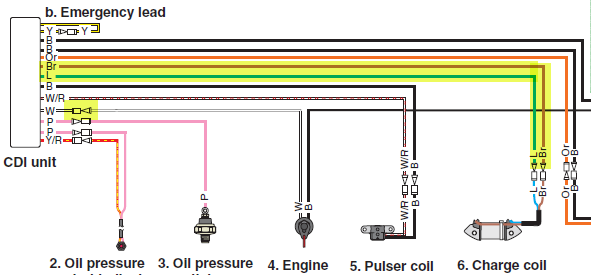
    However, I do remember reading a recent thread about the yellow "limp home" wire. Look at some recent posts or do a search for it - I'm sure it's there.

    2000 Yamaha OX66 250HP SX250TXRY 61AX103847T
    1982 Grady Weekender/Offshore (removed stern drive & modded to be an OB)

    Comment


    • #17
      Originally posted by G.Chandler View Post
      Yellow wire, how does it work as an emergency get home wire? It didn't work for me, engine would not start and had to be towed back too my slip. Im pretty sure that I have a electrical problem and have been doing the testing out of the shop manual but why the yellow wire and what is it supposed to do. There is not a drawing for the CDI internals.
      The CDI assembly is looking for various inputs. So that it can make certain adjustments. If the CDI receives incorrect inputs it can lose its mind. Causing the motor to run poorly or not at all.

      Disconnecting the yellow wire causes the CDI assembly to go into the fixed ignition timing mode. So hopefully the motor can start, run, and be used to get the boat back home.

      Why would a drawing of the CDI assembly internals be needed?

      Comment


      • #18
        if the charge coil is not putting out the voltage needed to the CDI, the CDI cannot send it on to the ignition coils to produce spark.
        and I am not sure if the CDI could tell when to send the spark without input from the pulser coils.
        so I think some failures will not let the motor run even with that yellow wire

        Comment


        • #19
          Thanks for the information. With regards to"why would I like a internal drawing of the CDI" is, I'm am curious person who understands and can read electrical schematics. Particularly when in the shop manual or owners manual doesn't explain what the yellow wires does when disconnected.

          Comment


          • #20
            taking a CDI apart would be very difficult to do see what all is in the potted material and do any repairs to it.
            I have never seen diagrams of them either.
            CDI Electronics makes aftermarket units for a lot of the CDIs,
            so they must know what is in them and how they work

            Comment


            • #21
              Thanks for the information. With regards to"why would I like a internal drawing of the CDI" is, I'm am curious person who understands and can read electrical schematics. Particularly when in the shop manual or owners manual doesn't explain what the yellow wires does when disconnected.

              Comment


              • #22
                Originally posted by G.Chandler View Post
                Thanks for the information. With regards to"why would I like a internal drawing of the CDI" is, I'm am curious person who understands and can read electrical schematics. Particularly when in the shop manual or owners manual doesn't explain what the yellow wires does when disconnected.
                I understand your curiosity. A good thing to have.

                The owner needs to know how to get the motor started in certain conditions. The mechanic needs to know how to trouble shoot the CDI assembly.

                The owner's manual and the service manual will all but never have information as to the details of a design circuit. Way over the level of even a sharp mechanic.

                https://www.google.com/search?q=cdi+...hrome&ie=UTF-8

                Comment


                • #23
                  Thanks, and I further my diagnostics. Using at Ideal 61-340 Digital VOM 600 CAT. III along with a ES Model 640 DVA and 2015 (I don't have a 2016) Service Manual and all of the drawings, wirings diagrams, location of components appears to be the same, I get the following readings:

                  Spark plug caps: Cap resistance (4.0-6.0 k ohms) my readings 5.8, 4.08 ohms. Ignition Coil: Primary Coil (0.225-0.345) my reading 0.3 ohms. Secondary Coil (6.80-10.20 k ohms) my reading 8.3 k ohms.
                  Pulser Coil: OPV @ cranking (unloaded) 7.0 V. my reading 14.0 V. OPV @ cranking (loaded) 3.5V. my reading 8.34 V. Resistance (240-360 ohms) my reading 319.6 ohms. Charge Coil: OPV @ cranking (unloaded) 140V. my reading 265.7 V. OPV Cranking (loaded) 160 V. my reading 12.97 V. Resistance (232.00-348.00ohms) my reading 299.1 ohms. CDI unit: OPV @ cranking (loaded) 140 V. my reading 0.2 mV.

                  I followed all of the directions and Tips in the manual, so is there something I’m doing wrong? Since there isn’t spark, the engine will not run of course. Readings were taken at 74deg.F.

                  Comment


                  • #24
                    looks to me like unloaded is good, but hooked up (loaded)it is not.
                    so maybe there is a problem inside the CDI or the kill switch wire is bleeding off the voltage to ground.
                    have you tried disconnecting that wire from the CDI to make sure it is not grounded somewhere along its path to the controls?

                    Comment


                    • #25
                      Yes. Try disconnecting the kill switch wire from the CDI assembly. Check the wiring from the charge coil to the CDI assembly.
                      Last edited by boscoe99; 02-03-2022, 11:09 AM.

                      Comment


                      • #26

                        Comment


                        • #27
                          Yes, I have disconnected the kill switch and checked it both with the spade to hold it open and with out. Reading with my VOM Open infinity and without 0 ohms (grounded). I also removed the kill switch itself disassembled to check to see if contacts were ok. That was the first thing that I did when I started trouble shooting. I still don't understand why I get double the OPV unloaded which is supposed 7.0 V and I get 14.0 on the pulser coil. and the same with the Charge coil readings OPV unloaded 140 V and I get 265.7 V? Especially with the resistance readings on both coils are within the designed tolerances. Is the unloaded cranking voltage for them the minimum and is there a maximum? Nothing in the manual speaks to that.

                          Comment


                          • #28
                            Bossco99, That is the same electrical schematic that I have. Now this is "not a problem" but "a challenge to overcome"!

                            Comment


                            • #29
                              no , there is no max
                              if it is below the minimum , that is a problem

                              did you check to see if the wires going to and from the kill switch are grounded

                              does this motor have a key switch, or a push to kill button?
                              how about a man overboard kill switch?
                              they all need to be checked along with the wires to them to see if they are grounded

                              Comment


                              • #30
                                Problem solved last Friday. Replaced the CDI Assembly after testing everything again. I had to dig deep in the old memory bank. I was in Uncle Sam's Navy (Almost 60 years ago) and was involved in electronics. I also found a good You Tube Video that showed the circuity inside a CDI. "CDI Capacitor Discharge Ignition Circuit Demo" for those who may be interested. Thank you all for your help and suggestions.

                                Comment

                                Working...
                                X