
 Tweet
Tweet
Originally posted by 99yam40
View Post
-
All I know is what I can see on the meter. Not understanding much of it.
-
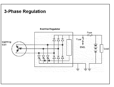
Now here is a diagram from Yamaha that shows the configuration for a three phase PMA. In which case the regulator is connected to the DC output.
A wye winding with the center point not being used.
Comment
-
Photos to follow this PM.Comment
-
OK so it is a Y set up and not a delta.
I guess those are zener diodes that bleed off excess voltage,
but I have no idea what the rectangle is that they are tied into.Comment
-
I believe the zener diodes are within the rectangle. That send current to the gates of the SCR's so they can close to shunt AC current to ground.
The Yamaha bigger lighting coils use a Y configuration. The 3 phase PMA that I have uses a delta configuration.
I lament not having an old Yamaha block with its flywheel and lighting coil installed so I could see what is to be seen with it. Oh well.Comment
-
Do SCRs allow current flow in both directions when the gate is closed?
still trying to figure out how the shunted voltage/current get back to the coils in the circuitsComment
-
You are asking questions well out of my pay grade.
My belief is that with no voltage to the gate there is no current flow through the SCR. Once the gate has a voltage applied to it (via the Zener diode I believe) the SCR allows voltage to be shunted from the coil to ground. Thus keeping the voltage down
https://www.electronics-tutorials.ws...thyristor.htmlComment
-
This seems to be a pretty good theory of operation for a shunt type of rectifier/regulator. Although it does not go into details as to how the switching from the AC to ground gets done. No mention of zener diodes or SCR's.
https://www.electrosport.com/pages/t...g-system-worksComment
-
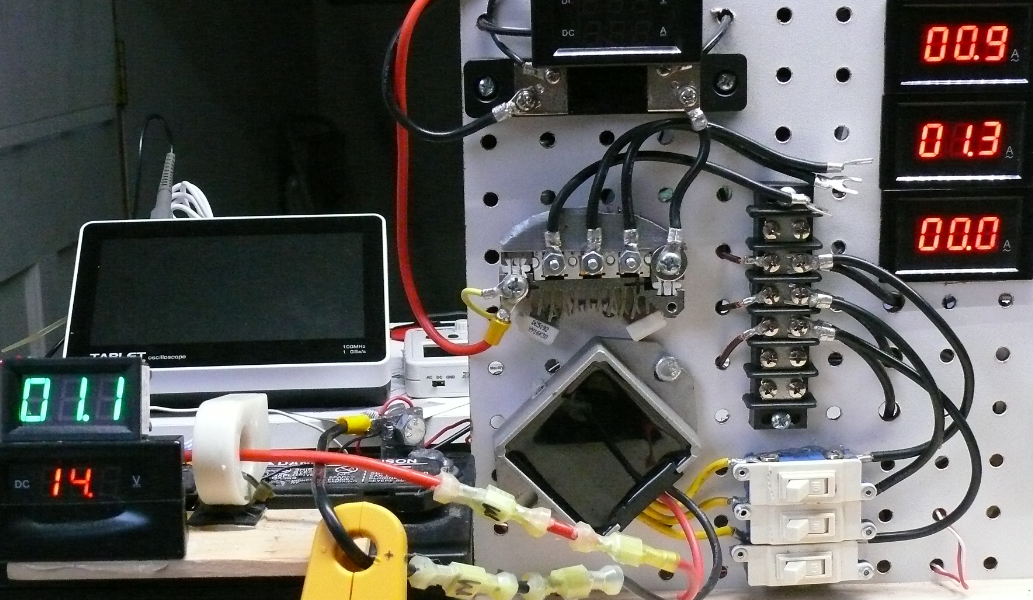
This is what I am seeing PMA current on. Hall effect sensors. Agrees with a clamp on meter.
Comment
-
I got my hands on a GE ECM electric motor out of my brothers HVAC air handler.
it is one of those variable speed 120/240V motors.
he kept it from his old unit when he got a new system installed.
I tried to find a way to run it without all the boards because he did not keep those.
only thing I found online was a way to test the motor my putting 240v for power and 24vAC control power on 8 of the 16-pin control c connector, but that did not make it turn.
So I decided to open it up to see what was inside.
there are 3 magnets glued to the rotor,
and lots of coils around the case(stater maybe).
there are 3 wires coming out of the back end that hook to another part stacked onto the motor.
on line they say it has 3 phase windings.
I hooked a meter to 2 of the wires and turned the motor by hand and got 4 - 5 v ac.
Need to come up with a way to spin it up and see what kind of voltage and current I can get out of it.
I will try to post a pic
GE ECM 2.3 motor 2.jpg
Comment
Comment