
 Tweet
Tweet
Hello,
I am trying to trouble shoot this issue and need some help as it’s my first time working on ignition system.
Engine was running perfect and then a few times cut out. Eventually it would not start again.
There is no spark getting to all three coils.
I did the below test following a service manual and then replaced the CDI as recommended. This did not fix the problem now I am stumped. Now wandering if o have done something wrong with the testing method or setting on the multimeter.
Any one tell me what I am doing wrong?? Or where to look next?
2017 85hp Enduro 2 Stroke
I am in Central America.
Tests done with Peak reading DVA adapter and meter.
Charger coil (Stator/Set de Bobinas)
Unloaded / Cranking
Red - blue - 220vDC 12-30VAC 63 ohm
Red - brown - 75vDC 1vAC 654 ohm
(Manual says test DC but this confused me as I thought it should be providing AC to the CDI??? So I provide both readings with meter set to DC and AC)
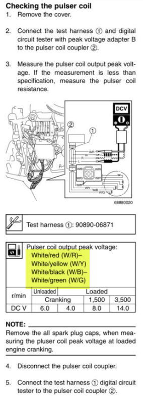
Pulser coil
Unloaded / Cranking
Red-Yel - 8.7vDC 332ohm
Black Green - 7.8vDC 322ohm
CDI to Coils
Loaded / Cranking (Spark plug caps off)
Cylinder 1 - 3v
Cylinder 2 - 3v
Cylinder 3 - 3v
Changed and charged battery
Cleaned and replaced all connections that looked corroded
Tested stop switch as per manual OK
Tested neutral switch as per Manual OK
Removed the pink and white cable connector to the CDI and tested CDI output to coils. No change.
Replaced CDI for new. No change.
I am trying to trouble shoot this issue and need some help as it’s my first time working on ignition system.
Engine was running perfect and then a few times cut out. Eventually it would not start again.
There is no spark getting to all three coils.
I did the below test following a service manual and then replaced the CDI as recommended. This did not fix the problem now I am stumped. Now wandering if o have done something wrong with the testing method or setting on the multimeter.
Any one tell me what I am doing wrong?? Or where to look next?
2017 85hp Enduro 2 Stroke
I am in Central America.
Tests done with Peak reading DVA adapter and meter.
Charger coil (Stator/Set de Bobinas)
Unloaded / Cranking
Red - blue - 220vDC 12-30VAC 63 ohm
Red - brown - 75vDC 1vAC 654 ohm
(Manual says test DC but this confused me as I thought it should be providing AC to the CDI??? So I provide both readings with meter set to DC and AC)
Pulser coil
Unloaded / Cranking
Red-Yel - 8.7vDC 332ohm
Black Green - 7.8vDC 322ohm
CDI to Coils
Loaded / Cranking (Spark plug caps off)
Cylinder 1 - 3v
Cylinder 2 - 3v
Cylinder 3 - 3v
Changed and charged battery
Cleaned and replaced all connections that looked corroded
Tested stop switch as per manual OK
Tested neutral switch as per Manual OK
Removed the pink and white cable connector to the CDI and tested CDI output to coils. No change.
Replaced CDI for new. No change.
Comment