Buy Yamaha Outboard Parts

Announcement

Collapse
No announcement yet.

Need 12v key on for gauges twin ox66

Collapse
X
 
  • Filter
  • Time
  • Show
Clear All
new posts

  • Need 12v key on for gauges twin ox66

    Hello there,

    I think this is a quite common issue but i wanted to check if my solution is feasible.
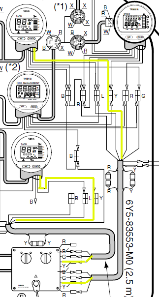
    The problem is how to power gauges and activate the power steering pump with 12v (yellow wire) when either or both outboards are on. The original setup only powers the system when the port engine is on.
    I'm using a small power busbar to connect all accessories fed by a yellow wire from each side with a diode inline. This worked fine when only one of the outboards was on but it blew both inline fuses when i tried running both motors at the same time. Thinking I'm using the wrong diode, i started digging around until i found these diodes used in the twin key switch:

    YAMAHA OUTBOARD KEY SWITCH DIODE 6K1-81980-00-00

    Would it be a good idea to power the busbar using these diodes, one for the starboard side and another for the port side?

    Thank you for your input.

  • #2
    It is easy to have either motor power the gauges when either motor is on and the other is off.

    Sounds to me, however, like you are trying to use the power supply to the gauges to provide power to a power steering pump. Which would exceed the current capacity of the yellow "key on power" wire. I think.

    Comment


    • #3
      The power steering pump has a wire for power on reference, the actual power feed wire is going straight to a 50 amp circuit. What's going to this power busbar is just the 12v reference.

      What's blowing the fuses is having both motors running simultaneously.

      Comment


      • #4
        Not too sure you need a diode? Also isn't there two sets of gauges, one for each motor? Maybe I am just missing what you mean!

        Comment


        • #5
          Originally posted by ausnoelm View Post
          Not too sure you need a diode? Also isn't there two sets of gauges, one for each motor? Maybe I am just missing what you mean!
          I think he is talking about the fact that one key being on applies power to one tachometer while the other key being on applies power to the other tachometer.

          And he wants to be able to turn off one motor or the other motor while continuing to have key on power to a common busbar. With diodes being used so that when one motor is off the other motor does not power up his instruments. I think.


          Comment


          • #6
            where is the busss getting power from?
            separate batteries or a single source?
            what feeds those batteries or batery?
            I would be checking that the diodes are good and they are installed correctly.

            is there a wiring diagram of how this is all hooked up, or did you just do this the way you thought it should be hooked up?

            Comment


            • #7
              I suspect diodes are used to isolate both systems including separate batteries, from each other.
              Fuses will probably blow when one side, without isolation goes to also charge the other battery when not intended, Two running engines will provide about the same voltage to each battery. When there is no isolation a stopped engine battery voltage drops, and it is this difference that causes enough extra current on the running engine for it’s fuse to blow.
              You need to trace each wiring setup.

              Comment


              • #8
                This is the setup, hopefully, this will illustrate what I was trying to explain. Notice that the PA draws under 1A, it's just for the system to know the power is on.
                Again, the issue is that when both motors are on the fuse in the yellow line are both blown.
                Should I be able to use the YAMAHA OUTBOARD KEY SWITCH DIODE 6K1-81980-00-00 in place of the diodes I have?

                2023-05-15_12-27-35.jpg
                Attached Files
                Last edited by mesias_yam; 05-15-2023, 01:12 PM.

                Comment


                • #9
                  If both fuses are blowing when the key on yellow wires are connected to busbar, but not when they are not connected to the busbar, then that is telling me something connected to the busbar is drawing excess current.

                  The fuses are rated at 10 amps as I recall.

                  Comment


                  • #10
                    The fuses are blowing when both yellow wires got powered, port and stbd switches were turned to on. When turning on one engine at a time, the fuses were not blown with the same load. That's what's confusing me. I'm suspecting the diodes I have are allowing some current to pass.

                    Comment


                    • #11
                      Are the motors running when this happens, they each are producing power from their alternators?

                      or is it just turning the key to the on position causes battery or batteries to blow the fuses, motors are not running?
                      you still have not said how many batteries you are dealing with.
                      some use one for each motor and also house batteries for running electronics.

                      your statement from above.
                      "What's blowing the fuses is having both motors running simultaneously."

                      Comment


                      • #12
                        I currently have a dedicated battery for each motor, one for port and one for stbd.
                        I'm sorry for the confusion, I never had both motors running at the same time while testing this setup. It was with the key in ON only. The fuses were blown when I switched the key to the ON position for both motors.

                        Comment


                        • #13
                          test the diodes to see if one or both is bad.
                          and make sure they are hooked in properly( not backwards)
                          I would think the diodes you listed should be OK to use as long as they are not powering the buss feeding the steering pump.
                          BUT I do not know what they are rated for

                          so just 2 batteries dedicated to each their own motor?
                          so what powers the steering pump?
                          Last edited by 99yam40; 05-15-2023, 03:57 PM.

                          Comment


                          • #14
                            I'm using THESE, they are rated for 15 amps... but yeah, I have to test them again.
                            In general, the concept of this setup is correct, right?

                            Comment


                            • #15

                              and what is the PA?

                              Well rereading things it seems both motors have a yellow wire feeding the buss, with diodes on each yellow wire.
                              the power steering pump is fed with a 50 amp circuit that we have no idea where it comes from.

                              some how we are suppose to see something only pulls 1 amp
                              Last edited by 99yam40; 05-15-2023, 06:37 PM.

                              Comment

                              Working...
                              X