
 Tweet
Tweet
Did you say that you still have an oscilloscope?
-
-
Just made it back from the property up above LaGrange, so Just saw your post.
yes, I have 2 very old ones that no longer work.
I am not sure how they will help. -
No workee = no damn bueno. Was wanting you to capture a wave form image from your lighting coil.Comment
-
this is voltage to ground, at idle,
on one leg, of one of the two lighting coils,
on my F225TXRD

Comment
-
Do you have one of a phase to phase?Comment
-
Why is Vmax so low?Comment
-
voltage between two legs ? no
what would that tell you?
Comment
-
quite possibly,Originally posted by boscoe99 View Post
that I don't understand how to use the settings correctly...
this was a"peak voltage" measured with a VOM at the same point, same conditions

Comment
-
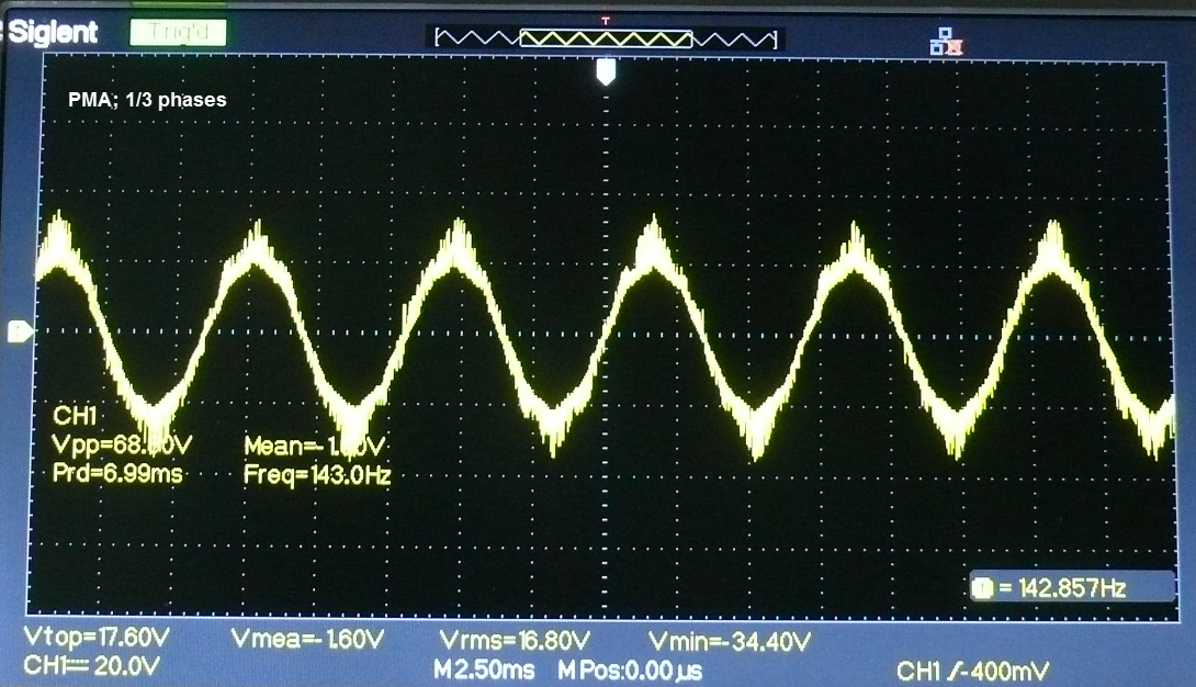
I am wondering if the display is indicating a Vmax of 15.67V with the 1 having been clipped off.
If a phase to phase measurement were to be taken I would expect to see a typical sine wave. Which I see from when measuring a 110 volt wall outlet or a single phase permanent magnet alternator that I have. The reason why I ask is because what I am seeing on my three phase permanent magnet alternator is looking most strange. As shown below.
Had not thought of measuring from a phase leg to ground. Will do that tomorrow to see if what I see is similar to what you have displayed.
 purple apple logo wallpaper
Comment
-
Boscoe I gather you are doing this as an educational exercise. I like people wanting to learn.
You said that the display is Strange. Yes it is but no reason to worry.
I think your sensitivity settings are telling you more than you want.
When venturing into the instrument world you’ve got to be more and more able to laterally think.
They are there to Visually give you information, it is not real eg. lines do not exist, but we like to see things with lines. To be as accurate as possible the artificial line needs to be absolutely thin barely visible, and even then the thickness of the line can be interpreted as meaning something, it does not.
Now all that fuzziness, distortion, misshape means something if you really want it too, because these instruments can delve deeper into things.
What I see is that perhaps there are reflections, resonations and Noise - a problem with how your probe is shielded etc.
There is also the problem that your alternator is actually speeding up, slowing down and Wobling through play in bearings.
I can go on, be mindful of all the interactions and factors when setting up any experiment- don’t let instruments get the better they (no matter how expensive) can mess with your mind!Last edited by zenoahphobic; 04-08-2022, 09:28 PM.Comment
-
I think that is a good thought.
did you not hook up the shield clip to help reduce the noise?Comment
-
The shield was connected.Originally posted by 99yam40 View Post
What I am guessing that it might be is the way that the magnets are installed in the rotor. They are slanted with respect to the axis of the rotor shaft.Comment
-
from what I have seen online of them making those things, it looks like they drill holes in rotors and glue the magnets in.
So mabe the magnets are not set in exactly the same position.
the drilled position, the depth of hole, and magnet strength may also produce variablesComment
-
I know you mentioned before ,the back end of the shielded lead was connected to ground at the scope,Originally posted by boscoe99 View Post
but I was thinking that the shield clip on the end of the lead needed to be also hooked up close to the place you attached the lead to ,to help minimize things like this also
Comment
-
Three phase alternator. Three output wires. Probe ground clip attached to one of the three phases. The other clip was attached to a different phase wire.Comment
Comment