Buy Yamaha Outboard Parts

Announcement

Collapse
No announcement yet.

Yamaha 30 x3 2 strk charging connector

Collapse
X
 
  • Filter
  • Time
  • Show
Clear All
new posts

  • Yamaha 30 x3 2 strk charging connector

    Hi!

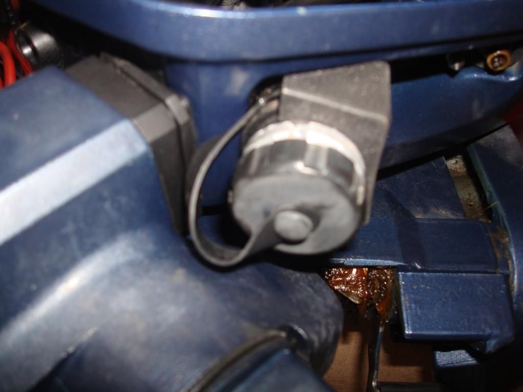
    Have this following connector from a 30 x3 30DMO/30MLH, 2 stroke that have 2 green wires coming from the lighting coil than R/R to this connector, so is suposed to be a charger for the battery, right?


    I'm converting this motor also for electric start and I'm considering install the push start botton here if this connector is not necessary which is my guess.
    Last edited by almetelo; 10-05-2014, 06:10 PM.

  • #2
    If that part is an electrical receptacle for wires coming from the rectifier/regulator, with one being red and the other being black, then my guess would be that it is for electrical power to be provided to a battery.

    Looks like a grommet was there originally for a manual start model.
    1995 C30MLHT Yamaha Outboard BOTTOM COWLING Diagram and Parts

    For an electric start model that is where the starter button switch is mounted.
    1995 C30MLHT Yamaha Outboard ELECTRIC PARTS 3 (30EH) Diagram and Parts

    Comment


    • #3
      Hi Boscoe!

      Just have 2 green wires coming from LC =ŧ R/R to the connector.
      Thats why I'm not sure what this connector does.

      But I'm sure I'll not need it (correct me if I'm wrong)

      Now just need the 2 green wires from LC to R/R, the red wire from R/R to starter relay with a fuse in the middle ( +/- how many amps fuse? 15a?) to positive of battery, neutral switch, push start botton etc

      Can I eliminate this connector and feat the push start botton here? I guess so...

      Comment


      • #4
        Is this connector:


        Part # 689-81870-00 aka 2P Concent

        what this is suposed to do?
        Last edited by almetelo; 10-05-2014, 06:11 PM.

        Comment


        • #5
          689-81870-00-00 is the starting switch assembly.

          1994 C25MLHS Yamaha Outboard ELECTRICAL 2 (C25ER - EH) Diagram and Parts

          Where do those green wires go that are shown leading away from your motor?

          Comment


          • #6
            Originally posted by almetelo View Post
            Hi Boscoe!

            Just have 2 green wires coming from LC =ŧ R/R to the connector.
            Thats why I'm not sure what this connector does.

            I am reading your words as you have two green wires going to the R/R from the lighting coil and then some wires going to the connector from the R/R. Is this correct? If so, and if the connector has just two pins or sockets, I would put a voltmeter on those pins/sockets. Start the motor up. Are you seeing approximately 14 volts or so?

            But I'm sure I'll not need it (correct me if I'm wrong)

            Now just need the 2 green wires from LC to R/R, the red wire from R/R to starter relay with a fuse in the middle ( +/- how many amps fuse? 15a?) to positive of battery, neutral switch, push start botton etc

            Can I eliminate this connector and feat the push start botton here? I guess so...
            That connector, in that location, does not look like anything I have ever seen. As noted in the illustration that I linked to above, it appears that is where a start switch goes in the electric start version of the motor.
            See comments above,

            Comment


            • #7
              yes, right!

              But I posted a wrong part #;
              IS 682-84381-00 and NOT 689-81870-00
              If is for charge a battery why 2 green wires and not a black and red wires out of the R/R

              Comment


              • #8
                I've got the answer...

                https://translate.google.pt/translat...405&edit-text=

                Translated russian to english by google translator

                But still donīt get why the 2 green wires instead of black/red wires

                Thanks

                Comment


                • #9
                  sent a previous post but gone for aprovement of moderator as had a link and may take a while...

                  I got the answer from this site

                  https://as.spinningline.ru/2012/06/0...l-na-motor-405

                  Had to use google translator to read it (russian to english)

                  Just still dont get why the 2 green wires out of R/R instead of a red/black wire

                  Comment


                  • #10
                    I think it is because it is an extension from the lighting coil that does not have the R&R.
                    Used to run lights so not regulated or rectified

                    This is my guess anyway

                    http://www.boats.net/parts/search/Ya...202/parts.html

                    Comment


                    • #11
                      The outside part is called a "lighting coil extension harness". Perhaps it was intended to be run to an externally mounted rectifier, a rectifier/regulator, or perhaps plain AC voltage was to be used for some lights?

                      Part number 682-84382-00-00.

                      Not something I am familiar with. Item 8 in this illustration.

                      2006 and Later Rigging Yamaha Outboard ELECTRICAL WIRE HARNESS 2 Diagram and Parts

                      Comment


                      • #12
                        Originally posted by 99yam40 View Post
                        I think it is because it is an extension from the lighting coil that does not have the R&R.
                        Used to run lights so not regulated or rectified

                        This is my guess anyway

                        2006 and Later Rigging Yamaha Outboard ELECTRICAL WIRE HARNESS 2 Diagram and Parts
                        I think you are correct. I should have read your post more carefully before I posted mine. Sorry.

                        Comment


                        • #13
                          99yam40 and Boscoe!

                          You're right guys!

                          Tested the connector and have AC voltage of 6v at idle up to 17.5v
                          works good for lights (of couse intensity of brightness change as increase or decrease rev's)

                          R/R seems also to be working good as battery have 12.7v and goes up to 13.8v when increase revīs (expected a little more voltage " al least my F100 charge up to 15v" but I guess is not a problem, right?)

                          Since I donīt need both AC and DC of battery Voltage Iīll remove the AC connector and feat there the push start botton.

                          Last question:

                          The fuse from R/R to the starter relay/Positive is suposed have +/- how many amps ? 15A?

                          Comment


                          • #14
                            20 amps is what my data shows.

                            Comment


                            • #15
                              boscoe has never worked with A/C lighting nor BSA or triumph moto sickles .
                              bet boscoe never delt with Lucas electronics.

                              there is a reason we called lucas the prince of darkness .

                              A/C lighting is simply that.
                              DC bulbs will deal with A/C current and like it.
                              with NO battery involved and NO DC rectification, it simply brightens and dims with rpm.
                              why??????
                              tell me HOW can you generate A/C voltage.

                              Comment

                              Working...
                              X