Buy Yamaha Outboard Parts

Announcement

Collapse
No announcement yet.

Problem with 2003 150 HPDI tach

Collapse
X
 
  • Filter
  • Time
  • Show
Clear All
new posts

  • Problem with 2003 150 HPDI tach

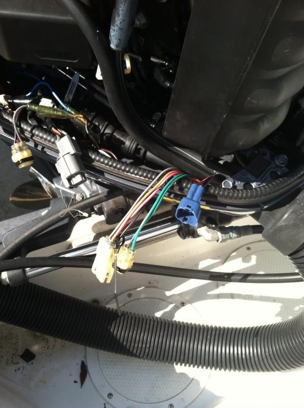
    My tach stopped working and I think it's a green signal wire prob from the engine. I can't get continuity from the tach to the green wire in the connector with the green wire and green/red wire (maybe brown not red). Is this supposed to be the tach signal wire in the engine, the connector to the right of the on with the zip tie? I tried bypassing the connectors under the console to see if I could continuity but still no luck, was going to try running a new green wire but have not been able to find anything to confirm this is the right wire.


  • #2
    The green wire shown in your photo is not for the tachometer signal. That green wire is used for a different function.

    Nothing like using the same coloured wire for different functions, or changing wire colours across a connector. Messes with a mechanics mind.

    The tachometer signal is in a green wire that is part of the ten pin harness. See illustration below:

    Comment


    • #3
      There is a bundle of 10 wires that go back to the engine but the weird thing is that if I try to get continuity from the green signal wire from the tach to any of the wires coming into the engine I don't get continuity. Shouldn't I get continuity on one of them regardless the color?

      Not sure if it makes a diff but my gauge is not a multi function type. It's just a tach with a green sig wire. The remote only has a green, blue, red and two brown wires going into it. So this diagram doesn't really make sense but that is about the same as what I have found searching elsewhere. The tach has worked fine until now, I have owned the boat since new so I know the wiring has never been messed with.
      Last edited by Jac197920; 07-26-2014, 01:56 PM.

      Comment


      • #4
        The wires are separated from each other by insulation.

        Why would you expect there to be continuity between the green wire and any other wire color?

        I would think that the continuity that you are interested in is from the tachometer green lead all the way to the ECU. The tachometer gets its signal from the ECU. There are several connection points along the way any one of which can result is a lost tachometer signal.

        If the tachometer is known to be good, and if the green tachometer wire has good continuity from the tachometer to the ECU then I would suspect that the ECU is faulty with respect to the tachometer signal output. Not likely, but...

        Comment


        • #5
          What I meant was if the wire changes color along the way I should get continuity on one of the wires regardless of the color. You even said "changing colors across connectors" and you are not the first person I have heard that from. I will take a look at the ecu connector and try pinning it there for continuity. I doubt the ecu is bad, the engine runs fine. I bet it's the tach but want to verify the sig wire is good first.

          Comment


          • #6
            Continuity is not based on wire color.

            My comment was based on Yamaha using green in two different applications. Green for the tachometer signal and green (the one in the photo) for oil system status lights. This defies conventional wisdom.

            I then went on to comment on Yamaha's propensity to also change wire colours along the way. If you note in the diagram I first provided, the green wire in your photo changes to another color (green/red) at the tachometer. Again, in contrast to good design practice.

            Comment


            • #7
              Sorry I misunderstood you about the 10 pin connector because there is a 10 pin connector under the console but also in the engine. When I pinned the green wire in the 10 pin in the engine I get continuity with the tach wire. So it's either the tach or the ECM. Don't you need an oscilloscope to see the tach signal? Or is there a way you can verify the tach is bad?

              Comment


              • #8
                Do you have a spare wall wart lying around that you no longer use? That is, a 120 volt AC to 12 volt DC transformer?

                It can be used to power a tachometer and also to provide a tachometer signal. Some dis-assembly required.

                Comment


                • #9
                  Yes, but I can power it on the boat. Going by what faria has to say you should see the needle jump when you apply 12 volts to it but not seeing that and they say you should see about 2 volts on the signal wire, not seeing that either. Just curious though about the wall wart thing you were saying. Is there a way to pulse the 12 volt signal with one of those? Or are you saying they naturally do that and most 12 volt components you use those for don't care?

                  Comment


                  • #10
                    A wall wart has a 120 volt coil on one side and a 12 volt coil on the other side. The 12 volt coil feeds a diode assembly that converts 12 volts AC to 12 volts DC.

                    The 12 volts DC will power the tachometer. You then jumper one side of the 12 volt AC coil to the tachometer and it will indicate RPM. 3600 RPM if my memory does not fail me. 60 hertz a second times 60 seconds a minute equals 3600.

                    I suppose I don't need to remind you to be careful with the 120 volt side of the transformer.

                    Comment


                    • #11
                      Ok tried that, tach still appears to be dead. The ac voltage on the transformer was only 10 volts at the most (for the signal wire) but it did have about 12 vdc on the output. It was a 12 vdc output as labeled but I guess it's not going to be exact. It sounded like the hertz was more important than the ac voltage, 10 volts was probably close enough? Going to order a new tach and hope that should fix it. Pretty good idea though, I never tore apart on of those wall warts as you call them. Thanks for your help, I will post the outcome when the new tach arrives.

                      Comment


                      • #12
                        wont work quite that way, the DC output is DC and WONT show hertz as its DIRECT CURRENT.
                        only A/C shows up as hertz or cycle per second cause its alternating current.
                        a quick test?
                        simply hook your meter leads to a good ground and the green send wire.
                        set up on DC or AC it really doesn't matter much.
                        start the engine,record the voltage,rev the engine slowly to about 2000 RPM,voltage should haave steadily increased.
                        if it did that junk tach is bad, if it did not further testing is nessasary.
                        the ECU generates the tach signal based on pulser coil inputs.
                        were not looking for a specific voltage just that it changes with RPM.
                        unlike other manufactures,yamaha wont give a test for tach circuits.
                        the setup used on the FICT motors the manual gives the test in Hertz and various RPM's,yamaha uses a voltage but its a varying pulsed voltage generated by the ECU.

                        Comment


                        • #13
                          Who said anything about connecting the tachometer input signal wire to the DC output of the transformer?

                          Comment


                          • #14
                            the way I read it he was going to use an AC to DC transformer,like a battery charger,to test the tach.
                            its kind of a confusing read.
                            I don't think I have ever seen a tach circuit failure on the V6 motors,its a low voltage low current setup that doesn't fail much.
                            I have seen many many Faria tach failures.
                            Faria also made them for OMC and BRP.
                            I cant tell you how many system check tachs I have pulled bad out of the box.

                            but still the fastest most reliable test is to unhook the tach send wire from the tach, find a KNOWN good ground, start the motor and observe the voltage.
                            it should rise and fall with engine RPM.

                            Comment


                            • #15
                              I was reading that problems with your tach are early signs of a bad rectifier. I just replaced my batteries, first time in 11 years of owning the boat. Not sure if that has anything to do with it. My Selco service manual has no tests for fuel injected motors. Is there anything I can do to test the rectifier? Or should I not worry about that? It's a Z150TXRB.

                              Comment

                              Working...
                              X