
 Tweet
Tweet
I have a 2003 Yamaha 115 2 Stroke TXRB with the 703 Control box. I am trying to install a 6Y5-8350T-D0-00 Tachometer. I used the 6Y5-83553-N0-00 gauge harness/2 fuse kit and the 68F-82553-70-00 2 plug wire harness from motor to the 2 plug Tachometer. Everything seems to be working on the tachometer except the Temperature Icon on the Gauge has one blinking bar on it. I am not sure if this is correct or not. If anyone has a wire diagram on this gauge or any information that would be great. On the trim sender that is mounted on the motor they have 3 wires(one is a short gray wire that isn't hooked up to anything). Is this gray wire supposed to be hooked up anywhere on the motor. They also have another gray wire with a black stripe with a large plastic sheeth cover of the connection coming out of the main wire harness on the outboard motor (is this wire supposed to be hooked to anything). Do any settings have to be done in the tach itself, It came with No instructions or wiring diagram. If anyone can lead me in the right direction it would be greatly appreciated. Thanks
-
-
for one thing, a new gauge would come set for 4-stroke / 2 wire trim sender
so you need to set the dip switches correctly
see page 5-8 of this document
http://www.moto-m0t0.ru/riggingguide2008.pdf
there are also some wiring diagrams in the same section
but I think we will need Boscoe to answer your other questions -
Thanks for your response, I will have to look to see if they have dip switches on this gauge. I didn't notice them when I installed it. Is there an email contact for Yamaha Outboard rigging to get instructions for this Tach. It seems for the money you spend on these gauges it would come with some type of instruction manual.Comment
-
Instructions for use of the tachometer is included within the owner's manual that was provided with the motor. If another copy of the OM is needed it can be obtained from any Yamaha outboard motor dealer. Or from https://www.yamahapubs.com/results.p...15TLRB&lang=en
The over temperature icon should not normally be blinking. Winking or nodding either.
Instruction for installation of the tachometer is included within the Yamaha Outboard Rigging Guide. To which fairdeal has provided a link.
I suspect that the tachometer is set for the four stroke mode. Adjust it per the ORG and then let us know what you see.
Ignore the gray wire lead from the trim sender.Last edited by boscoe99; 05-15-2019, 08:12 AM.Comment
-
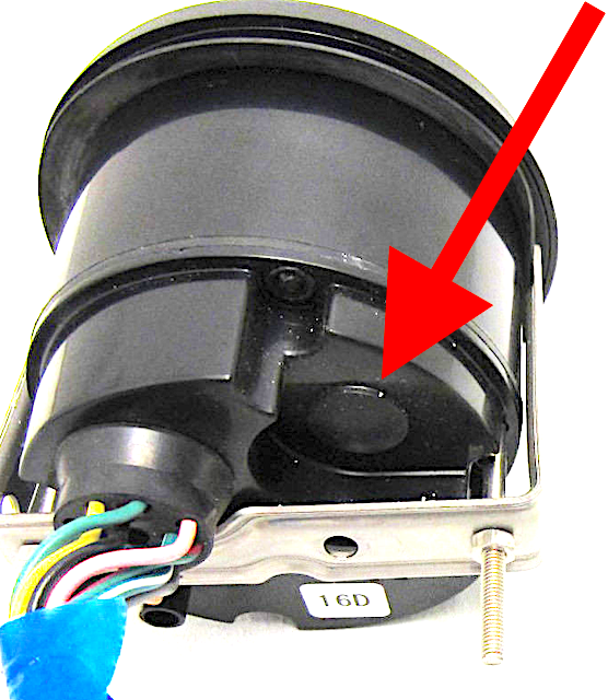
pry out the rubbery plug on the back, then look down inside for the dipswitches
I think you will need to remove it from the dash
Comment
-
Hold on, I previously went through this and Boscoe helped me, then when I was rigging a set of 2005 HPDI's I had to reconfigure it again.
Under the cowling on the stbd side, there is a gray wire that is likely not connected through the plugs.
HISTORY: I replaced my washed out LCD gauges with new ones. The older ones, worked as advertised, but when I installed the new gauges (newer revision) to the same wiring harness, I had the fault that I believe you described. I would perform the test by shorting (connecting) the temperature switch wires that came from the sensor in both cylinder heads. While it did make the horn sound, it did not flash the BAR under the thermometer icon.
**NOTE my engines had a single temp sensor (for the ECM only) and two temp switch (for the overheat alarm only) I would not suggest shorting the singular temp sensor, (although it likely would cause little or no harm)
On my 2000 SX/LX150TXRY's I had to fashion a wire that had a female sumitomo four contact plug on one end and a female barrel connector on the other. This plugged into a previously unused four way connector in the wire harness and an unused gray barrel connector on the engine.
When I repowered with the 2005 HPDI's (LZ / Z200TXRD) I removed the barrel connector and terminated a female sumitomo contact that was added to another plug (I think the trim sensor) that was in use in this current configuration.
Basically, I completed the GRAY wire path through the existing connectors, both times. Luckily for me I have a collection on Sumitomo and other Yamaha type connectors and parts for just such repairs.
Please return and let us know what works to correct your discrepancy. By reporting back, other may find this information helpful in the future.
Cheers!
I source my connectors through easternbeaver.com in Japan.Last edited by FabricGATOR; 05-15-2019, 12:13 PM.If its got teats or tires, you bound to have trouble with it....Comment
-
Perhaps I am wrong. I did just correct my problem last week when I made changes, but Boscoe99 has not steered me wrong in the past. I acquiesce to his greater experience.Originally posted by boscoe99 View Post
Please let us know, so we all know.
And do check the dip switch configurations as initially suggested.
If its got teats or tires, you bound to have trouble with it....Comment
-
So I was able to check the dip switches and sure enough it was set to 4 stroke. I changed to correct settings and everything seems to be correct. I did find out that my trim switch(plastic lever) is broke so the trim gauge isn’t working yet, ordered a new trim sender. Tach, temp, and oil all seem to be working. Thanks for everything, I will update once I get a final install on trim sender.Comment
-
Another weak link in that is the plastic clamp / collar that mounts to the tilt tube (fulcrum) (steering tube) You may consider getting that part too. There is an updated version that is made of metal.Originally posted by Lilrock24 View Post
Thank you Lilrock24 for the info on the dip switches and the setting for four stroke being the fault with your tachometer display.
Cheers!.If its got teats or tires, you bound to have trouble with it....Comment
-
I got my new trim sender in today, but the new trim sender had a 3 wire plug, plus the gray wire and my original had 2 wire plug, plus the gray wire. I installed it anyways along with the new metal collar instead of plastic. When first installed it would not properly track on the trim gauge. I pulled the gauge once again and set the dip switch to a 3 wire trim sender, and it’s now tracking properly. So currently Trim, Temp, Oil, and tach seem to be correct. I believe all I have left is to install the blue wire from gauge to my gauge backlight switch with all my other gauges and I should be good to go. I will post a picture of the gauge when I get to go out in the boat. Thanks for all your help.Comment
-
A 115TXRB should have had a two wire sender. But if you installed a three wire sender, and have set the tachometer accordingly, and it works, then all is well and good.
Now when a two wire sender is mentioned, the reference is to the two wires that are attached to the sender itself. There may be other wires at the connector.

Comment
-
That is some good info right there. I am glad to be subscribed. When I installed the Z200, I noted the trim sensor and installed the metal trim collar/tang with hope of the system working on my investment in new tachometers. When they did not work, I simply dismissed it as bad sensors. Now I have something else to try to improve...Originally posted by boscoe99 View Post
Thank you folks.
If its got teats or tires, you bound to have trouble with it....Comment
-

Comment
-
I have a 2003 F115 4-stroke with the 6Y5 type of tach. It has been working flawlessly since I got the boat 2 years ago. However, 2 weeks ago, it began to be intermittent and now only shows 0 RPM. It also appears as though the hour meter is not working but the T/T indicator is working. It is my guess that the signal wire from the engine to the tach has a break but I am uncertain which is the signal wire from the engine. Can I run a test lead from the engine to the tach to see if there is a possible break?Comment
Comment