Buy Yamaha Outboard Parts

Announcement

Collapse
No announcement yet.

1997 Yamaha 225 Saltwater II Battery question

Collapse
X
 
  • Filter
  • Time
  • Show
Clear All
new posts

  • 1997 Yamaha 225 Saltwater II Battery question

    I just bought a used Cobia with a 225 Saltwater V6. Started going thru the power systems and found an A-B - ALL switch. When I look in the Yamaha book on this engine it shows 2 batteries but no switch. The book talks about this engine is able to charge 2 batteries but the layout to me just does not seem right.

    Battery A - Pos goes to starter relay - Neg is ground on starter. Battery A goes no further.
    Battery B - Neg to Battery A Neg - Pos goes to Accessories

    How does Battery B get charged? If the Pos is feeding Accessories is Battery B some how charged thru the accessories? should I forget the book and just continue to use the A/B/All switch?

    I can the diagram from the book if that would help.

    Thanks for the help

  • #2
    Originally posted by dmwascher View Post
    The book talks about this engine is able to charge 2 batteries but the layout to me just does not seem right.
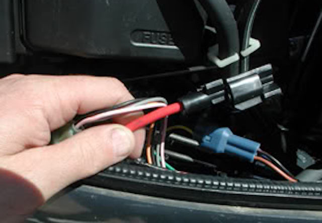
    Perhaps the book is referring to the optional "small charging cable" as described by Yamaha :


    On the harness of your engine there is a short red wire - the "auxiliary" aka "isolated" charging lead,
    which is provided in order to charge a second battery solely for "Accessories"
    using an optional Yamaha wire
    (in the diagram above, "the small charging cable")
    which connects between the engine and that second battery.
    (negatives of both batteries are grounded together)

    In that scheme there is no need for a switch;
    however, it does not permit 'selecting' the Accessory battery to start the engine.

    Comment


    • #3
      Wow. Now that sounds better. My book said nothing about that. Do you know where that wire comes off of? Is there a connector or wiring harness that it comes off of?
      it does sound like if needed I could still use a deep cycle as Battery 2 and run a 2nd Pos lead to a switch to flip and start the engine if Battery 1 is dead.

      thank you so much for responding.

      David w

      Comment


      • #4
        You should see it coming from the rectifier/regulator. Red and capped off

        Comment


        • #5
          It should be laying in bottom cowling on the starboard side.

          Comment


          • #6
            It's possible you're just not tracking all the wires correctly (where they go). From what you wrote, for example, it sounds like your existing battery switch is not connected to anything. Maybe there's either a wire laying in the bilge not connected or you just haven't made complete sense of it, yet. Try this - run the engines and check the voltage at each battery with a meter. If that battery switch IS hooked up, put it in different positions while you monitor the voltage at each battery.

            FYI, if you have the Service Manual (it's likely the same as mine), there is mention of the charging lead in the charging section of the manual.
            2000 Yamaha OX66 250HP SX250TXRY 61AX103847T
            1982 Grady Weekender/Offshore (removed stern drive & modded to be an OB)

            Comment


            • #7
              here is how the Yamaha 'auxiliary charging lead' can be connected using a "Dual Circuit Plus" switch.

              the switch turns both cranking and house batteries on/off simultaneously
              They are normally separate, but there is a switch setting to 'combine' if desired.
              In either setting, both batteries receive charging current from the engine.

              Comment


              • #8
                Originally posted by dmwascher View Post
                Wow. Now that sounds better. My book said nothing about that. Do you know where that wire comes off of? Is there a connector or wiring harness that it comes off of?
                it does sound like if needed I could still use a deep cycle as Battery 2 and run a 2nd Pos lead to a switch to flip and start the engine if Battery 1 is dead.

                thank you so much for responding.

                David w
                What is the complete model of your motor?

                Comment


                • #9
                  Originally posted by fairdeal View Post
                  here is how the Yamaha 'auxiliary charging lead' can be connected using a "Dual Circuit Plus" switch.

                  the switch turns both cranking and house batteries on/off simultaneously
                  They are normally separate, but there is a switch setting to 'combine' if desired.
                  In either setting, both batteries receive charging current from the engine.

                  I may not remember. Doesn’t the aux wire attach to pole with red headed to house battery? Versus fuse block? Maybe the switch diagram is throwing me off.

                  Comment


                  • #10
                    Originally posted by pstephens46 View Post

                    Doesn't the aux wire attach to pole with red headed to house battery? Versus fuse block? Maybe the switch diagram is throwing me off.
                    the layout seems a bit odd to me, also - I modified a Blue Sea diagram.

                    But simply for getting the engine current to the house battery,
                    it doesn't matter at all whether you connect the Aux lead direct to the battery,
                    to the battery side of the switch, or the 'load' side of the switch.

                    Comment


                    • #11
                      Does it seem to anyone that the myriad ways of connecting a motor to a battery(s) (banks if you will) seems to be way more complicated than it should be? Question after question after question is posted about this matter. Now I recognize that one size does not fit all but it surely (shirley?) seems to be more complicated than necessary.

                      Is this a result of various manufacturer's trying to come up with more clever switches and combiners/ACR's/VSR's?

                      Years ago we used one battery with one motor. No switch. From there it has evolved (not necessarily for the better) to what appears to me to be a Rube Goldberg configuration.

                      Comment


                      • #12
                        My Model number is S225TXRV and I have uploaded the diagram from my book. I will be looking today and see if I can find the port or the red wire that everyone says I should have and get back to everyone.
                        Thanks to everyone that is commenting


                        . 20190327_224325.jpg

                        Comment


                        • #13
                          After looking on the starboard side I only have a BLUE wire cap'ed off no red wire

                          Comment


                          • #14
                            from your schematic, seems to me there is a second - presumably isolated- output from the regulator/rectifier


                            and looking up the r/r for your engine, there are indeed two red output leads:


                            but so far, I can't find the connector for the Aux lead on the engine wiring harness itself...

                            Comment


                            • #15
                              in somewhat more modern times, it look like this:


                              Comment

                              Working...
                              X