Buy Yamaha Outboard Parts

Announcement

Collapse
No announcement yet.

Help with Lcd marine meter

Collapse
X
 
  • Filter
  • Time
  • Show
Clear All
new posts

  • Help with Lcd marine meter

    Hi folk, this is my first post so forgive me if im not greatest in description.
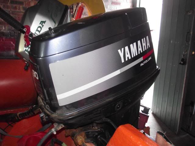
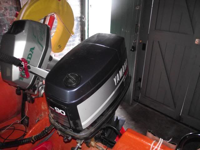
    I own a 90hp Yamaha autolube maybe early 90's model, this is run from the 703 controls.
    Problem I have with being novice and not an electrician is I have the old lcd marine meter , it does not have function buttons.
    I desperately need help on wiring this up to the cable that is from the controls.
    many thanks
    graham

  • #2
    Why are you desperate? This is not a critical issue. Relax a bit and we will solve the problem.

    Does the marine meter have round or square plastic connectors coming from the back?

    Do you just want just the tachometer function to work or do you also want the lights to illuminate to indicate the oil system status?

    What is the complete identity of the motor. We are not mind readers. The serial number will start with the number 6. Should be on a decal on the left hand clamp bracket.

    Comment


    • #3
      Engine serial number is hard one as the plate is not there, I will post pictures tomorow when I go over to garage, then gives chance for experts to help

      Comment


      • #4
        Take a photo or two of the connectors that are in the engine pan. Should be up front.

        Is the motor in use now?

        Comment


        • #5
          motor worked before we did full refurb on rib, trim works from 703 control etc
          and engine fires up.

          Comment


          • #6
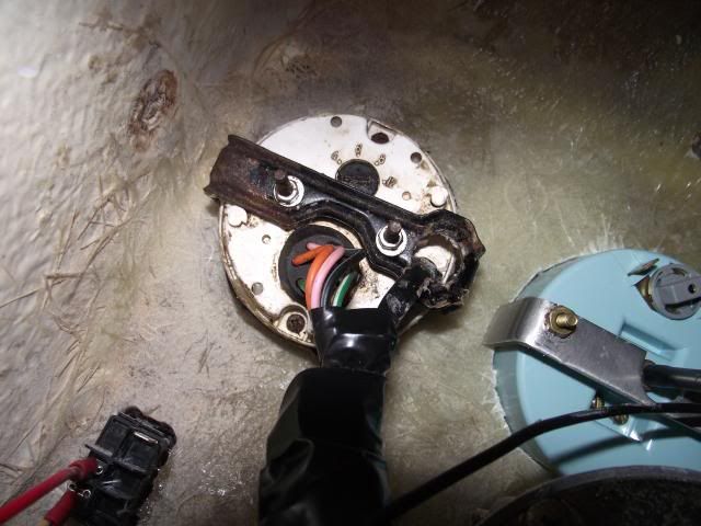
            Pics of lcd meter


            Comment


            • #7
              engine yam 90hp autolube


              Comment


              • #8
                The photo of the tachometer wires is not as clear as it could have been. Hard to see the single green wire for the tachometer signal. Should have a bullet connector on the end. I see that one green wire appears to have been cut.

                See following diagrams. 12 volt positive and ground, plus the tachometer reference signal get to the tachometer from the 703 control box via a small harness.

                There should be another harness that runs from the motor directly to the tachometer connector (the round plastic one) for the oil system status lights. That harness should have round connectors at each end.

                Comment


                • #9
                  what is to round dial for with numbers 4,6,8 & 12 for????

                  Comment


                  • #10
                    Originally posted by boscoe99 View Post
                    The photo of the tachometer wires is not as clear as it could have been. Hard to see the single green wire for the tachometer signal. Should have a bullet connector on the end. I see that one green wire appears to have been cut.

                    See following diagrams. 12 volt positive and ground, plus the tachometer reference signal get to the tachometer from the 703 control box via a small harness.

                    There should be another harness that runs from the motor directly to the tachometer connector (the round plastic one) for the oil system status lights. That harness should have round connectors at each end.

                    Hi these drawings are great many thanks
                    can you explain what the lamp switch is?????
                    is this so tacho is lit up when ignition is on?????

                    Also what do the blue and black (lights) wires hook up too???
                    Last edited by Gramas80; 12-29-2013, 06:38 PM.

                    Comment


                    • #11
                      The lamp switch is used to turn on or off the internal tachometer lighting. Some connect the tachometer light to the boats navigation lights switch so that when the boats lights are turned on the gauge lights come on.

                      Or, the gauge wiring can be configured so that the internal lighting is on whenever the key switch is on. Just remove the switch shown in the diagram and connect the blue wire to the yellow wire.

                      Or, the gauge can be connected to nothing at all in which case the internal light will not be used.

                      The blue and black wires come from the tachometer and are for the internal lighting within the tachometer. As stated above, they can be connected in a number of different ways or they can not be connected to anything at all.

                      Comment


                      • #12
                        Originally posted by Gramas80 View Post
                        what is to round dial for with numbers 4,6,8 & 12 for????
                        It is set the tachometer to a particular motor. The numbers refer to the number of magnet poles in the flywheel. Different Yamaha motors have a different number of poles.

                        A 90 HP two stroke Yam has 12 poles. So, with your motor it would be set to the 12 position. Otherwise the RPM indication on the tachometer will not be correct.

                        Comment


                        • #13
                          So if I want background light to come on when ignition is on I need to take away the light switch and join the yellow wire & blue wire together, the lights wires blue an the black which are in separate sleeve become redundant???? Just put caps on them and tape them out way

                          Comment


                          • #14
                            Yes.

                            The other black and blue wire connectors are for other gauges if you have them installed.

                            Comment


                            • #15
                              Boscoe you have been so helpful to me, if I get stuck I will post more questions
                              Thank you

                              Comment

                              Working...
                              X