Buy Yamaha Outboard Parts

Announcement

Collapse
No announcement yet.

Yamaha CommandLink Plus LCD display V2 fuel gauge calibration

Collapse
X
 
  • Filter
  • Time
  • Show
Clear All
new posts

  • Yamaha CommandLink Plus LCD display V2 fuel gauge calibration

    Hey all ... new here ...

    I'm having a bugger of a time with a new CL+ V2 (VERSION:6Y90F20P0150656) unit's fuel gauge functionality ... the initial builder / dealer settings (including Logs > Maintenance - 100 Hour Service interval completed confirmation) got wiped out by button pushers (this is a SAR FRC crewed by several operators) ...

    FYI - fuel tank sending unit is a Scepter (ABYC) sending unit (12"-24"), part # 07152 (Moeller part # 035729-10). Single 1/4" aluminum fuel cell is 200 US gallon capacity.

    Apparently, the fuel tank / gauge calibration must be done on an empty tank (with a full tank, I keep getting the following calibration attempt error message: "Sensor has Invalid range", and, the fuel tank level just flashes one bar at the bottom with no percentage value shown in Other Views > Tanks).

    The only documented methods I have read:

    Single Point Calibration (0% full, ie. empty)

    or, Multi Point Calibration (0%, 25%, 50%, 75% & 100%), where, during a fill of an empty tank, five different calibrations are made, the first while empty, the rest at each successive fuel volume pumped:

    ie. for (200 US gallon tank - 5% for expansion =) 190 US gallon normal operational full capacity ... at 0, 47.5, 95, 142.5 & finally 190 USg's pumped

    My current plan, short of getting advice about some other calibration method(s) here, is to utilize the sending unit empty resistance spec, 240 ohms, and see if I can calibrate the CL+ fuel tank (gauge) level (while the actual tank remains full of fuel) by disconnecting the sender leads, putting a 240 ohm resistor in circuit between them (physically / electrically independant of the actual sender terminals) and proceeding with a CL+ Single Point Calibration.

    This would be accomplished by: switching all batteries off, disconnecting both leads at the sender, introducing the resistance (240 ohms for empty / 0% full) into the circuit, then powering up again once all connections are secure, performing a CL+ Single Point Calibration, powering down, restoring original sender connections and finally testing the calibration result - the CL+ fuel tank (gauge) level should show full or very close to it.

    Comments?

    Also, how does one access Dealer level functionality and where is this documented? My Canadian CL+ manual is '6Y9-2819U-31-E0'.

    Thanks

  • #2
    Version II software was not one of Yamaha's brightest moments. As in, what in the hell were they thinking?

    You do not have to disconnect and reconnect the batteries to calibrate the fuel aval functionality and/or fuel level bar scales. Just go into the display and follow the calibration set up menu.

    First, make sure that of the four tank possibilities, only the tank(s) in your boat is(are) set to fuel. If other tanks are set to fuel they must first be set to some other functionality such as water, waste or generator.

    Either get another sender(s) and attach it(them) to your sender lead(s) or use a resistor as you have mentioned. Then follow the set up procedure.

    I presume that you know that you have to go into the menu and select Fuel Aval as one of the fields that are to be shown on the display.

    Some folks are not happy that the display indicates 90% of the tank capacity when the tank is full. To over come this multiply the tank quantity by 1.1111. Insert this value into the gauge as your tank size. When full the gauge will now indicate 200 gallons as being available and not 180 gallons.

    Most dealers don't know a damn bit more about setting up a CL+ display than a customer does.

    Comment


    • #3
      Originally posted by boscoe99 View Post
      Version II software was not one of Yamaha's brightest moments. As in, what in the hell were they thinking?
      It did not take Yamaha too long to "fix" Version I, so why don't they fix Version II? I have Version I and will NOT "upgrade" to V2.

      Is there an online manual for the Version II gauge, all I can find is the V1.

      Comment


      • #4
        Originally posted by tmann45 View Post
        It did not take Yamaha too long to "fix" Version I, so why don't they fix Version II? I have Version I and will NOT "upgrade" to V2.

        Is there an online manual for the Version II gauge, all I can find is the V1.
        Not that I know of.

        Comment


        • #5
          Hey boscoe .. thanks for stepping up and helping me out ...

          --> batteries --> all on rotary battery switches, so, not a big deal to turn them off

          --> only the one (fuel) tank to be configured ... do I still need to go into the others (presumably at defaults - is the default fuel?) and set them to other than fuel?

          --> we are getting Fuel Aval as part of the COMBO A display, and, it can also be viewed from Menu > Other Views > Tanks

          --> for "Some folks are not happy that the display indicates 90% of the tank capacity when the tank is full.", in our case, with a 200 g tank that is normally only to be filled to 190 g (to allow for 5% expansion), would an appropriate over-capacity calibration be 211.109 (190 x 1.1111), or, 222.22 (200 x 1.1111)? I'm guessing if we want to see the gauge saying full at 190 g, it should be the former.

          F

          Comment


          • #6
            tmann ... I tried uploading the 4.27MB Canadian CL+ V2 PDF manual three times to this forum ... no dice ... PM me your e-mail and I'll send it along to you.

            F

            Is it me, or is this site slooooow?

            Comment


            • #7
              boscoe ... or someone who knows fuel sender unit electrical characteristics (for a Scepter 07152 / Moeller 035729-10) ...

              I went ahead with my plan to do a CL+ Single Point Calibration using a (1/2 Watt) 240 Ohm resistor between the disconnected fuel sender leads (to simulate an empty tank) ... but did not get the results I expected.

              When power came up on the gauge with the resistor in circuit all by itself, I selected COMBO A view and initially noted the fuel tank gauge reading bars were all filled in blue ... like the tank was full! Strange ...

              Anyways, I went in and set Tanks 2, 3 & 4 to Unused, and then went in to Tank 1, set it to Fuel, ABYC, set my tank capacity and proceeded with a Single Point Calibration attempt, I once again got the error message "Sensor has Invalid range". Disappointing ...

              I used a multi-meter to check the resistance between the exposed metal surfaces of the lead connectors themselves (with the resistor in place) and got my expected 240 Ohms (actually 238.8 Ohms), so OK there.

              I then checked the resistance between the unconnected fuel sender terminals (tank was probably about 3/4 full of fuel at the time, to the best of my knowledge, so, was expected to read around 85~ Ohms give or take) and was surprised to find the resistance was on the order of 38.5~ KiloOhms. I checked the resistance between the fuel sender ground terminal and the tank / tank ground strap and found no resistance there.

              Q. On a previous occasion, I know one of my colleagues pulled the ground lead off the fuel sender ground terminal (without pre-advice to me, or consent from me, while I was at the helmsman's position futzing with the CL+ gauge) while the gauge was powered up ... would that be enough to damage the fuel sender unit?
              Or, shudder to think it ... the CL+ gauge itself?

              And, to clarify, when I am performing my resistor substitution trick, should I be providing an extra path to ground on the ground lead side of the resistor connection? Or does the existing ground lead actually terminate at ground back up at the bus near the gauge (obviating the need for a redundant ground)?

              Thanks guys,

              F

              Comment


              • #8
                I presume that you have the sensor leads (for the number one tank) disconnected from the sender when you are using the resistor as a simulation device. Further, that tanks 2, 3 and 4 have been set to either water, waste or generator.

                When you are jumpering the sender wires with a resistor, yes the ground wire going back to the CL+ display must be grounded as well to the ships ground. The same ground, that is, that is applied to the display. Strange, but that is the way that it is.

                I will outline what I believe to be the set up procedures. See if this is what you have and what you have been doing.

                1. Go into the menu, to Settings, to Initial and then to Tank Set. Press the Set Button.
                2. Set tanks 2, 3, 4 to something other than Fuel. Set tank 1 to fuel.
                3. Set sensor type to ABYC.
                4. Highlight the calibration window and then press the set button.
                5. Highlight the Individual Tank Capacity window and press the Set Button.
                6. Add the tank capacity. Use either actual tank capacity (in which case 90% of this will be shown) or use the tank capacity times 1.1111 to display the actual tank capacity. Press the Set Button.
                7. Highlight Single Point Calibration window and press the set button.
                8. With the resistor installed on the sender leads (and the sender lead grounded as noted above) press the Set Button.
                9. You will get a confirmation message. Press the Set button to confirm.

                If this does not work, get back to us.

                Comment


                • #9
                  Originally posted by Frankenstien View Post
                  tmann ... I tried uploading the 4.27MB Canadian CL+ V2 PDF manual three times to this forum ... no dice ... PM me your e-mail and I'll send it along to you.

                  F

                  Is it me, or is this site slooooow?
                  Somehow this slipped by me. PM being sent, thanks.

                  Comment


                  • #10
                    Originally posted by Frankenstien View Post
                    boscoe ... or someone who knows fuel sender unit electrical characteristics (for a Scepter 07152 / Moeller 035729-10) ...

                    And, to clarify, when I am performing my resistor substitution trick, should I be providing an extra path to ground on the ground lead side of the resistor connection? Or does the existing ground lead actually terminate at ground back up at the bus near the gauge (obviating the need for a redundant ground)?
                    F
                    You need to supply an extra ground, as you put it, back to the battery negative.

                    Electrical characteristics for standard fuel senders, which the Moeller model you stated is:
                    Approximate values: Empty = 240 ohms, 1/2 = 103 ohms, Full = 33 ohms.
                    More info on standard senders/gauges at this site: Troubleshooting Teleflex Fuel Gauges
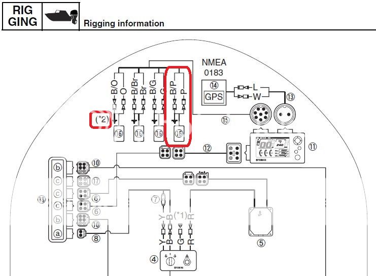
                    Wiring diagram, this illustrates what Boscoe said:


                    As per the wiring diagram, you should be using the Pink and Black/Pink wires back to the CL+ Display for tank #1, and the B/P should also be going back to the battery negative just like Boscoe said. I would try this using the resistor to test the gauge. Also note that the Display has a large damping factor, if changing the resistance from 33 to 240 ohms it might take 30-seconds for the gauge to respond.

                    Comment


                    • #11
                      best I remember 240 ohms would indicate empty and 35 ohms indicate full.

                      cant remember details like I used to.

                      but it would explain your meter readings on the sender.

                      Comment


                      • #12
                        One other thing I forgot to mention. Before doing the calibration setting delete all previous calibration settings. Then proceed to single point calibrate the gauge using your 240 Ohm resistor.

                        Comment


                        • #13
                          Hey guys ... thanks for all the help, info and diagrams ...

                          I can try the 240 Ohm resistor trick again with the extra ground and see what happens.

                          I can also check to ensure the Pink & Black/Pink wire pair (Tank 1) is being utilized up at the gauge bus.

                          I'm still concerned about the health of the existing fuel tank sender (resistance reading is 38.5 KiloOhms or 38,500 Ohms). That reading just doesn't make sense for a partially full tank ... unless the sender is pooched. I know that the fuel tank itself (& sender ground terminal - I tested continuity between it and the primary tank ground tab) all share a common ground by way of some 00 sheathed cable.

                          F

                          Comment


                          • #14
                            38,500 Ohms is way out of range. Did you check the sender with everything disconnected from it?

                            The Ohm's check should be across the two terminals only that are on the sender.

                            When in use, the ground terminal on the sender also has to be connected to the ships ground.

                            33 to 240 is the range for a US sender.

                            Comment


                            • #15
                              Yup ... all disconnected

                              Comment

                              Working...
                              X